project

This is another simple interfacing circuitry with the microcontroller. In this circuit we interface the mechanical relay with the microcontroller. Relay interfacing is very important and common type of interfacing which occurs in most of the microcontroller projects. Relay is basically electrically operated switch and act as a switching device to turn on and off the devices connected to the microcontroller, as well as provide isolation between the microcontroller and the operating device, assume we have to turn on and off the high voltage load then we cannot directly interface the device to the microcontroller as it can burn the microcontroller so we use Relay as a switch and isolator. We can control the high voltage devices with low power control signal. Logical operation can also be obtained by connecting relays in different combinations, In the early ages before the invent of vacuum tubes and transistor relays wee used as an logical element in the early computers.

The working mechanism of the relay is very simple. Relay works electromagnetically when the control signal given to the relay the magnetic flux produces in its coil either made the contacts to get apart or connect with each other. There are many types of Relay available differs in their type of application and working for example:

Latching relay

Reed relay

Mercury-wetted relay

Polarized relay

Machine tool relay

Contactor relay

Solid-state relay

Solid state contactor relay

Buchholz relay

Forced-guided contacts relay

Overload protection relay

etc

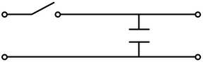
In our circuit we are using Latch Relay.


For circuit diagram and the coding click the link given below:

Download attachment

16 Segment display is a alphanumeric display segment which helps us to display the English, Thai, Persian and other characters. These segments are now use in many applications and the gadgets having display panel like calculators,telephone Caller ID units, gymnasium equipment, VCRs, car stereos, microwave ovens, slot machines, DVD players and other embedded systems. This circuitry is another simple interfacing of the 16 segment with the microcontroller. Interfacing of the various elements is the basics of the beginners of microcontroller learners.

In this circuit we use microcontroller AT89C51 and 16 segment display. We display the characters from (A to Z) first and then numbers (0 to 9).

For circuit diagram and the coding click the link given below:

Download attachment

Show the following patterns on the 7 Segment display

1) Ascending Order (0-9)

2) Descending Order (9-0)

3) Odd numbers

4) Even numbers


This is another simple circuitry to interface the Seven segment to the microcontroller. It is one of the basic circuits which helps the beginners to understand the interfacing of microcontroller with basic elements. In this project we use microcontroller AT89C2051 and 7 segment common anode.

7 Segment consist of 8 LEDs connected in a way that they can display the numbers from zero to nine (0 to 9) with a decimal point . There are basically two types of seven segments Common Anode Seven Segment and Common Cathode Seven Segment, In common anode we connect the common terminal of  the seven segment to 5 volts and to glow any segment we connect it to the ground, while in the common cathode configuration we connect the common terminal of the seven segment to the ground voltage and to glow any segment we connect it to the 5 volts.

In this circuit we first display the number in ascending order then in descending order then the odd numbers and finally the even numbers on the seven segment display

For circuit diagram and the coding click the link given below:

Download attachment

This is another simple circuitry to interface the Seven segment to the microcontroller. It is one of the basic circuits which helps the beginners to understand the interfacing of microcontroller with basic elements. In this project we use microcontroller AT89C2051 and 7 segment common anode.

7 Segment consist of 8 LEDs connected in a way that they can display the numbers from zero to nine (0 to 9) with a decimal point . There are basically two types of seven segments Common Anode Seven Segment and Common Cathode Seven Segment, In common anode we connect the common terminal of  the seven segment to 5 volts and to glow any segment we connect it to the ground, while in the common cathode configuration we connect the common terminal of the seven segment to the ground voltage and to glow any segment we connect it to the 5 volts.

This circuit display the digits from zero to nine on the seven segment.


For circuit diagram and the coding click the link given below:

Download attachment

Blinking LEDs in Sequence:

This is another basic introductory circuit of micrcontroller. In this circuit we turn on and off the leds in sequence bu using microcontroller AT89C2051, one LED is on at one time then after some delay it becomes off and another LED turns on and so on. There are two ways to do this sequence in assembly language. First way is to turn on one port and keep other ports off at one time then turn on second port and keep other ports off and so on. Second way to do it is by load the value 01111111(07FH in hexadecimal) to the register and then rotating the value in the register, every time after one rotation the rotated value is moved to the port 1.

For circuit diagram and the coding click the link given below:

Download attachment

Here is a simple circuitry which will help you to understand how will you interface and LED with a micro-controller. The code is written to turn on and off the LED after some short delay, this is one of the beginning circuit when one tries to gain some hands on the micro-controller interfacing. This circuit help beginners to learn through the micro-controller course which we will provide you by exploring you some of the introductory circuit with the micro-controller. It is the best approach to get started with the Atmel family of Micro-controllers, because they are easy to understand and does not contain too much complexities.
in this circuit we are using AT89C2051 micro-controller and just an LED. The other components like resistor,capacitors and crystal are the prototype configuration with the micro-controller and used in almost every configuration of the Micro-controller.

For circuit diagram and the coding click the link given below:

Download attachment

Sample and Hold

Sample and hold circuit is the first step in the process of analog to digital conversion. It actually takes samples of the analog signal at specific time intervals depending on the clock frequency. Clock frequency is the frequency at which we are taking samples of the analog signal. Basically sample and hold process comprises of two steps:

  1. Take samples
  2. Holding samples


Samples are taken at the clock frequency while the hold step is accomplished by connecting the capacitor in the parallel to the output of the sampled signal. The simple sample and hold circuit is given below


The switch is on whenever we want to take sample and capacitor helps to hold that sample. Practrically the switch is implemented by connecting the fast switching FET switch, and samples are taken on some clock frequency which can be implemented by any timer circuit. The capacitor is invariably discharged by its own leakage current.


In our project we are taking audio signal frequency as the input signal. for sampling the input signal we must have sampling frequency twice of the bandwidth of the input signal. This is given by the sampling theorem. This theorem states that the sampling frequency must be the twice of the bandwidth of the input signal. If the sampling frequency is below the twice of the input signal bandwidth then aliasing of the samples will occur. Aliasing refers to an effect that causes different signals to become indistinguishable when sampled. The aliasing if the samples can be observe by taking the Fourier transform of the samples or by viewing the samples in the frequency domain. The higher the sample rate the more accurate the analog information will be in digital form and so the bandwidth. The higher sample rate has higher accuracy. The aliasing of the samples are describes in the figure given below

Components used in the project are as following:-

JFET BF245C:

The JFET BF245C is the simplest type of field effect transistor. It can be used as an

electronically-controlled switch or as a voltage-controlled resistance. Electric charge flows through a semiconducting channel between “source” and “drain” terminals. By applying a bias voltage to a “gate” terminal, the channel is “pinched”, so that the electric current is impeded or switched off completely.


Diode

Capacitors

Resistance

Power Supply

Function Generator:

The sampling clock is given to the gate channel of the JFET by the function generator or any timer circuit. The sampling frequency has its limitation which is describe by the sampling theorem.


Output waveform:

The output waveform of the simulation of sample and hold circuit is given below:


To download the circuit diagram click the link given below


Download attachment