Here is a simple circuitry which will help you to understand how will you interface and LED with a micro-controller. The code is written to turn on and off the LED after some short delay, this is one of the beginning circuit when one tries to gain some hands on the micro-controller interfacing. This circuit help beginners to learn through the micro-controller course which we will provide you by exploring you some of the introductory circuit with the micro-controller. It is the best approach to get started with the Atmel family of Micro-controllers, because they are easy to understand and does not contain too much complexities.
in this circuit we are using AT89C2051 micro-controller and just an LED. The other components like resistor,capacitors and crystal are the prototype configuration with the micro-controller and used in almost every configuration of the Micro-controller.
Electrical Projects
contains electrical projects
Sample and Hold
Sample and hold circuit is the first step in the process of analog to digital conversion. It actually takes samples of the analog signal at specific time intervals depending on the clock frequency. Clock frequency is the frequency at which we are taking samples of the analog signal. Basically sample and hold process comprises of two steps:
- Take samples
- Holding samples
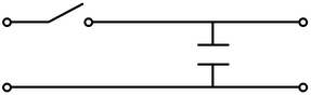
Samples are taken at the clock frequency while the hold step is accomplished by connecting the capacitor in the parallel to the output of the sampled signal. The simple sample and hold circuit is given below
The switch is on whenever we want to take sample and capacitor helps to hold that sample. Practrically the switch is implemented by connecting the fast switching FET switch, and samples are taken on some clock frequency which can be implemented by any timer circuit. The capacitor is invariably discharged by its own leakage current.
In our project we are taking audio signal frequency as the input signal. for sampling the input signal we must have sampling frequency twice of the bandwidth of the input signal. This is given by the sampling theorem. This theorem states that the sampling frequency must be the twice of the bandwidth of the input signal. If the sampling frequency is below the twice of the input signal bandwidth then aliasing of the samples will occur. Aliasing refers to an effect that causes different signals to become indistinguishable when sampled. The aliasing if the samples can be observe by taking the Fourier transform of the samples or by viewing the samples in the frequency domain. The higher the sample rate the more accurate the analog information will be in digital form and so the bandwidth. The higher sample rate has higher accuracy. The aliasing of the samples are describes in the figure given below

Components used in the project are as following:-
JFET BF245C:
The JFET BF245C is the simplest type of field effect transistor. It can be used as an
electronically-controlled switch or as a voltage-controlled resistance. Electric charge flows through a semiconducting channel between “source” and “drain” terminals. By applying a bias voltage to a “gate” terminal, the channel is “pinched”, so that the electric current is impeded or switched off completely.
Diode
Capacitors
Resistance
Power Supply
Function Generator:
The sampling clock is given to the gate channel of the JFET by the function generator or any timer circuit. The sampling frequency has its limitation which is describe by the sampling theorem.
Output waveform:
The output waveform of the simulation of sample and hold circuit is given below:

To download the circuit diagram click the link given below
Download attachment
Introduction
Here we are designing and implementing the four way traffic control system using TTL logic.
There are different variations of traffic control. The most common ones that are seen are signs (board), road lines, islands (division between opposite lanes of vehicles), and traffic lights. The first one mentioned is easily understandable. Human sight translates a drawn sign, understands what it means and thus follows it. The second one, road lines, is also uncomplicated. A road line demarcates or delineates the allowable areas and lanes that a vehicle can occupy. And a road line shows where a car cannot go, cannot make a U-turn or overtake another vehicle. Islands do the same things.
Now a days due to ever increasing vehicles on the road, it require a efficient control on the four way junction of road. In order to find a solution to this problem the concept of an automatic traffic controller is conceived. Apart from providing efficient control of traffic, it also eliminate chance of human errors since it function automatically.
Features:
Traffic lights involve a rather complicated automated system that relies on sensors and programs. There are basically two types: the first type of traffic light has fixed time. That means, the green light may be on for a minute and off for the next few minutes while the rest of the traffic lights turn green. There is a fixed time for every street meeting at an intersection. And there is the variable type of traffic light. The variable type of traffic light relies on sensors underground that detect the flow of traffic approaching the intersection. If traffic is heavy, the green light stays longer than it would if the traffic were light. Coupled with the traffic light are the speed detector and the red light running detector. The speed detector uses a device that registers the speed of an oncoming vehicle. The latter, the red light running detector uses cameras that capture vehicles’ plates as they cross an intersection. The addition of this device was due to the rise in the number of crashes that occurred because of drivers beating the stoplight.
Basic Implementation:
The basic implementation of this project is:
1. The automatic traffic controller automatically switches on the four way junction for 8 seconds for direction control.
2. The main circuit components used are 555-Timer and 4-bit binary synchronous counter (74160).
3. The 555-Timer generates a clock signal for 8 seconds. This signal is used to clock counter circuit.
4. Binary counter is converted to 3 bit–counter to achieve 8 possible cases. The traffic light control is done by different Boolean function of logic gate.
Project Report
Datasheets:
74LS160
555 Timer IC
7404
7432
7408
7411
Circuit Diagram:
Download attachment
Overview
Abstract:
To develop DIGITAL CLOCK using 7 segment display. It show hours and minutes. Make it by using discrete components.
Introduction:
A digital clock is a type of clock that displays the time digitally. Digital clocks are often associated with electronic drives, but the “digital” description refers only to the display, not to the drive mechanism.
Basically a digital clock requires these basic elements or blocks
- A source of power to run the clock
- An accurate timebase that acts as the clock’s heartbeat
- A way to gear down the timebase to extract different components of time (hours, minutes, seconds).
A way to display the time
WORKING OVERVIEW:
At the heart of the clock there is a piece that can generate an accurate 60-hertz (Hz, oscillations per second) signal. There are two ways to generate this signal:
- The signal can be extracted from the 60-Hz oscillations in a normal power line. Many clocks that get their power from a wall socket use this technique because it is cheap and easy. The 60-Hz signal on the power line is reasonably accurate for this purpose.
- The signal can be generated using a crystal oscillator. Obviously, any battery-operated clock or wristwatch will use this technique instead. It takes more parts, but is generally much more accurate.
The 60-Hz signal is divided down using a counter. A typical TTL part to use is a decade counter. This part can be configured to divide by any number between 2 and 10, and generates a binary number as output. So we take our 60-Hz time base, divide it by 10, divide it by 6 and now we have a 1-Hz (1 oscillation per second) signal. This 1-Hz signal is perfect for driving the “second hand” portion of the display. Similarly by configuring the decade counter we can produce the minute hand and hour hand also.
To actually see the output of the counters we need to drive a display. The two counters produce binary numbers. The divide-by-10 counter is producing a 0-1-2-3-4-5-6-7-8-9 sequence on its outputs, while the divide-by-6 counter is producing a 0-1-2-3-4-5 sequence on its outputs.
We want to display these binary numbers on something called a 7-segment display. A 7-segment display has seven bars on it, and by turning on different bars we can display different numbers. To convert a binary number between 0 and 9 to the appropriate signals to drive a 7-segment display, we use a “binary number to 7-segment display converter.” This chip looks at the binary number coming in and turns on the appropriate bars in the 7-segment LED to display that number.
Project Report:
Datasheets:
74LS160
74LS10
74LS20
74LS47
555 Timer IC
Circuit Diagram:
Download attachment
Abstract:
This is a simple project of making a digital clock using microcontroller AT89S51. The clock is in 12 hour format with am and pm function. The time is displayed on 2*16 character LCD.
Datasheets:
AT89S51
Working Video:
The link for project files is given below
Download attachment
Abstract:
The purpose of this project is to implement a simplified version of a robotic arm. This arm uses three motors: one to control the horizontal rotation (about z-axis) of the arm, second and third to control the vertical rotation (up & down movement).
Servo motors are used in robotics whose position is controlled by varying the duty cycle of the waveform applied. This project uses the Hitec HS-311 servos which operate between 4.8-6V, require a 50 Hz (20ms time period) square waveform, and are controlled using Pulse Width Modulation. These motors can rotate through an angle of 180 degrees max. A positive cycle duration of 0.9ms corresponds to an angle of -90 degrees and approx 2.1ms positive cycle corresponds to +90 degrees. The position or angle in between varies linearly with the duration of positive part in between 0.9-2.1ms. Hence, for example, a 50 Hz square wave with peak duration of 1.5ms would move the servo to 0 degree.
This project uses the AT89S52 microcontroller. This controller has 3 timers and each timer is used to control one servo. Every timer is used to apply a 50 Hz square wave on one output pin with the appropriate duty cycle to move the corresponding servo to its desired position. 6 buttons are connected to 6 input pins such that 2 buttons each control the direction of rotation of one servo, i.e. one button moves the motor in one direction and the other moves the motor in opposite direction. Further details and project report is given below
Datasheets:
AT89S52
The project is simulated in PROTEUS.
The link for simulation files of the project is given below
Download attachment
A simple project of digital code lock system. The basic user lock is of 5 Digits and Master Lock is of 10 digits so its not easy for an intruder to break the lock unless you keep the code simple.
The input is taken from a 4×3 Keypad (please see the schematic for more information) and Display the user input on a 2×16 LCD. A pin is assigned as output for activating and deactivating the lock. For demonstration I have connected an LED to that pin. Further details and working description of the project are given below
Datasheet:
AT89C2051
Working Video:
To download the schematic,code and other files click the link below:
